1. Standard parts and specifications The selection meth […]
1. Standard parts and specifications
The selection method of standard specifications for molds is best to consider the following items: (A). When the specifications used are not restricted, it is best to use the highest level. (B). In principle, standard numbers are used. (C). When the standard part of the mold does not have this size, use the closest one for processing.
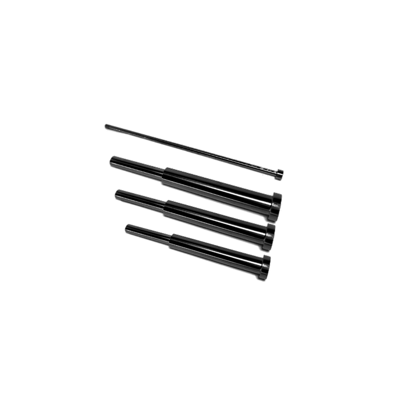
2. The design of the punch
Punches can be roughly divided into three parts according to their functions: (A). The tip of the cutting edge of the processed material (the cutting edge has irregular, square, round shapes, etc.). (B). The contact part with the fixed plate of the punch (fixed part or shank, the cross-sectional shape of which is irregular, square, round, etc.). (C). The connecting part of the blade and the handle (middle part).
The design basis of each part of the punch is briefly described from (A). Length of the cutting edge, (B). Grinding direction of the cutting edge, (C). The fixing method of the punch and the shape of the handle.
3. The design of the punch fixing plate
The thickness of the punch fixing plate is related to the size of the die and the load. Generally, it is 30~40% of the length of the punch, and the length of the punch guide should be 1.5 times higher than the diameter of the punch.
4. Design of guide pin (punch)
The diameter of the guide pin (punch) and the gap between the guide hole of the material, the size and the amount of the protruding pressure plate are designed according to the thickness of the material. The shape of the tip of the guide pin is roughly divided into two types: A. Cannonball Shape, B. Conical (push-pull shape).
(1). The shell shape is the most common form, and there are also standard parts on the market.
(2). The conical shape has a certain angle, which is very suitable for high-speed stamping of small parts. The determinants of the push-pull angle are the stamping stroke, the material of the processed part, the size of the guide hole, and the processing speed. When the push-pull angle is large, it is easier to correct the position of the processed material, but the length of the push-pull part will become longer. The connection between the push-pull part and the cylinder part should be smooth.
If you have any questions about plastic mold parts, please feel free to contact us and we will get back to you within 12 hours.
 English
 简体中文
简体中文


